Loads
Nodal Load
Nodal loads allow users to simulate external forces or prescribed displacements and rotations acting on specific points in the structure.
Concentrated Force and Moment
A concentrated force can be specified in the X and Z directions, as well as a concentrated moment load around the Y axis. The values are defined within the global coordinate system in the currently selected units. To make directional adjustments, users can append a negative sign to the specified values.
Loads can be added within the Bottom Bar section in the Loads tab, accessed by selecting the Add Nodal Load button. Nodal loads can also be added in the menu accessed by clicking the desired node.
Prescribed Displacements and Rotations
Prescribed displacements can be specified in the X and Y directions, while the prescribed rotation angle is specified around the Y axis. These values are defined within the global coordinate system in the currently selected units. To make directional adjustments, users can append a negative sign to the specified values.
Prescribed displacements and rotation is added within the Bottom Bar section in the Loads tab, and initiated by selecting the Add Nodal Load button and furthermore selecting Prescribed displacement checkbox.
Element loads
Uniformly Distributed Load
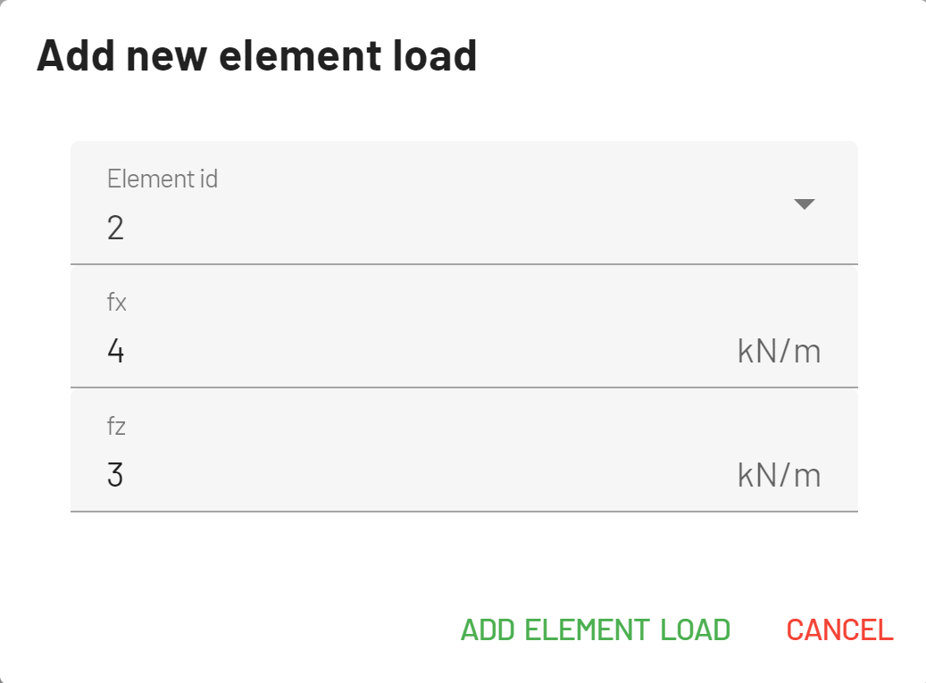
The Uniformly Distributed Load applies a uniform distributed load across the entire length of the structural element.
Component specifications can be in either the global coordinate system or the local coordinate system of the element.

Linearly Distributed Load
The Linearly Distributed Load represents a trapezoidal distribution of forces along the length of the structural element.
Component specifications can be in either the global coordinate system or the local coordinate system of the element.
Temperature load
The Temperature Load models the effects of temperature changes on structural elements. The software generates a temperature load vector for each element node, considering the coefficient of thermal expansion and the specified temperature change.
The two different cases of temperature loads in structural analysis are commonly referred to as:
Uniform Temperature Change: This represents a uniform temperature change applied across the entire structural element. The magnitude of temperature change is constant throughout the element. The load elongates or contracts the beam alogn its central axis.
Non-uniform Temperature Load: This represents a difference in temperature between the top and bottom fibers of the structural element. The load bend the element along the Y-axis.
In edubeam the Temperature Load is defined by specifying the temperature of the top and bottom fibers. Both cases and the corresponding load vectors are automatically calculated.
It is possible to ignore the effects of the Uniform Temperature Load.